

 CN
CN


 Home
Home
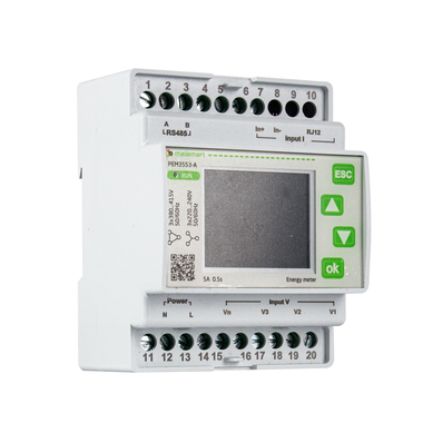
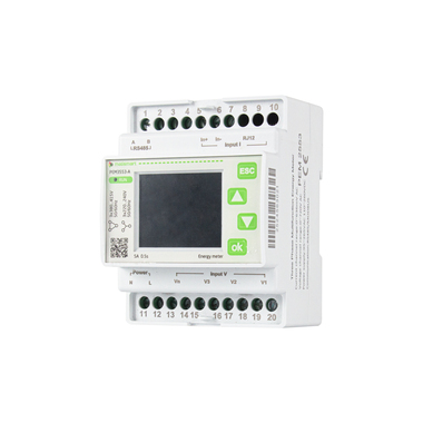
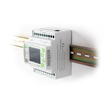
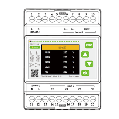
Three-phase Multifunctional Power Meter
PEM Series
PEM meter features:
·Multiple metering wiring modes, strong compatibility
·High-precision power parameter measurement
·Smart relays and digital inputs
·Comply with international measurement standards
·Strong environmental adaptability, suitable for harsh working conditions
·Powerful communication capabilities, supporting industry standard protocols
·Compact structure, easy installation

|
|
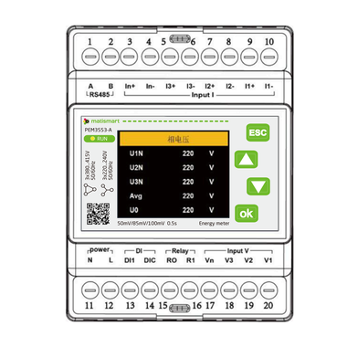
PEM3353-A
|
PEM3553-A
|
PEM3353-D
|
PEM3553-D
|
PEM3353-H
|
PEM3553-H | |
|
CT connection
|
Screw terminals
|
Rogowski Coil
0-900mVAC peak, 636 mV RMS
|
Screw terminals
|
Rogowski Coil
0-900mVAC peak, 636 mV RMS
|
Screw terminals |
Rogowski Coil
0-900mVAC peak, 636 mV RMS
|
|
|
Rogowski coil
|
- |
50mVkA@50Hz(0-12000A), @60Hz(0-10000A)
85mVkA@50Hz(0-7000A), @60Hz(0-6000A) 100mVkA@50Hz(0-6000A), @60Hz(0-5000A)
|
- |
50mVkA@50Hz(0-12000A), @60Hz(0-10000A)
85mVkA@50Hz(0-7000A), @60Hz(0-6000A) 100mVkA@50Hz(0-6000A), @60Hz(0-5000A)
|
- |
50mVkA@50Hz(0-12000A), @60Hz(0-10000A)
85mVkA@50Hz(0-7000A), @60Hz(0-6000A) 100mVkA@50Hz(0-6000A), @60Hz(0-5000A)
|
|
|
Metering wiring mode
|
3P4W-4CT / 3P4W-3CT / 3P3W-3CT / 3P3W-2CT/1P3W-2CT / 1P2W-1CT
|
||||||
|
Measurement voltage
|
L-N: 0 ~ 600VAC
|
||||||
|
Frequency range
|
45-65 Hz 1P+N, 3P,3P+N
|
||||||
|
Measurement accuracy
|
Current measurement accuracy
|
0.1%+ current sensor accuracy | |||||
|
Voltage measurement accuracy
|
±0.2%(60V~600V AC)
|
||||||
|
Grid frequency
|
±0.01% (45~65Hz) power factor ±0.005
|
||||||
|
Active and apparent power
|
IEC62053-22 class 0.5S
|
||||||
|
Reactive power
|
IEC62053-21 class 1S
|
||||||
|
Active energy
|
IEC62053-22 class 0.5S
|
||||||
|
Reactive energy
|
IEC62053-21 class 1S
|
||||||
|
Environmental conditions
|
Operating temperature range
|
-20℃ ~ +70℃
|
|||||
|
Storage temperature range
|
-40℃ ~ +85℃
|
||||||
|
Humidity
|
5~95% RH,50℃ (non-condensing)
|
||||||
|
Pollution degree
|
Pollution degree 2 (in accordance with IEC 60664-1)
|
||||||
|
Overvoltage capability
|
Overvoltage category III for power distribution systems up to 277/480VAC or 400/690VAC (in accordance with IEC 60664-1)
|
||||||
|
Dielectric strength
|
Complies with IEC 61010-1, withstand voltage AC 4kV / 1min
|
||||||
|
Altitude
|
≤ 3000m (in accordance with IEC 61010-1)
|
||||||
|
Protection class
|
IP20 (in accordance with IEC 60529)
|
||||||
|
Digital signal
|
Relay output
|
1 electromagnetic relay output, contact capacity: 3A 30V DC, 3A 250V AC
|
1 electromagnetic relay output, contact capacity: 3A 30V DC, 3A 250V AC
|
1 electromagnetic relay output, contact capacity: 3A 30V DC, 3A 250V AC
|
|||
|
Digital input
|
1 dry contact input, optocoupler isolation (5kVrms)
|
1 dry contact input, optocoupler isolation (5kVrms)
|
1 dry contact input, optocoupler isolation (5kVrms)
|
||||
|
Communication
|
Modbus; Communication rate: 2400bps~38400bps; Protocol: Modbus-RTU
|
||||||
|
Mechanical characteristic
|
Dimensions
|
94.5mm(length)*72mm(width)*65mm(height)
|
|||||
|
Measurement standards
|
EN 62052-11, EN61557-12, EN 62053-21, EN 62053-22, EN 62053-23, EN 50470-1, EN 50470-3, EN 61010-1, EN61010-2, EN 61010-031
|
||||||
|
PEM3353-A
|
PEM3553-A
|
PEM3353-D
|
PEM3553-D
|
PEM3353-H
|
PEM3553-H
|
|
|---|---|---|---|---|---|---|
|
CT connection
|
Screw terminals | RJ12 port | Screw terminals | RJ12 port | Screw terminals | RJ12 port |
|
Auxiliary power supply
|
95-265V AC 110~370V DC
|
95-265V AC 110~370V DC
|
18~36V DC | 18~36V DC | 90-528V AC | 90-528V AC |
|
Instantaneous value measurement
|
Phase voltage:U1, U2, U3, AVG, U0 (zero sequence voltage) Line voltage:U12, U23, U31, AVG
Current :I1, I2, I3, AVG, In
Frequency :F1, F2, F3, ∑ (comprehensive)
Power factor:PF PF1, PF2, PF3, ∑ (comprehensive)
Fundamental power factor:DPF DPF1, DPF2,DPF3, ∑ (comprehensive)
Active power:P1, P2, P3, ∑ (total)
Reactive power:Q1, Q2, Q3, ∑ (total)
Apparent power:S1, S2, S3, ∑ (total)
|
|||||
|
Energy measurement
|
Positive active energy:EP1, EP2, EP3, ∑ (total) Negative active energy:EP1, EP2, EP3, ∑ (total)
Positive reactive energy:EQ1, EQ2, EQ3, ∑ (total)
Negative reactive energy:EQ1, EQ2, EQ3, ∑ (total)
Apparent energy:ES1, ES2, ES3, ∑ (total)
Tariff energy:ET1, ET2, ET3, ET4, ET5, ET6
When the energy reaches 1.0 x10⁹ kWh, the energy will automatically reset
|
|||||
|
Harmonic
|
Voltage harmonic percentage:Total harmonics (U1, U2, U3), total odd harmonics (U1, U2, U3), total even harmonics (U1, U2, U3), sub-harmonics 1-50 (U1, U2, U3)
Current harmonic percentage:Total harmonics (I1, I2, I3), total odd harmonics (I1, I2, I3),
total even harmonics (I1, I2, I3), K factor (I1, I2, I3), sub-harmonics 1-50 (I1, I2, I3)
Voltage harmonic value: Total harmonics (U1, U2, U3), sub-harmonics 1-50 (U1, U2, U3)
Current harmonic value:Total harmonics (I1, I2, I3), sub-harmonics 1-50 (I1, I2, I3)
|
|||||
|
Phase diagram
|
Phase diagram:Phase diagram display between voltage and current Phase sequence:Voltage, current
Voltage angle:U1,U2,U3
Current angle:I1,I2,I3
Voltage and current angle:UI1,UI2,UI3
|
|||||
|
Demand
|
Demand:Total active power, total reactive power, total apparent power Maximum total active power maximum demand:Maximum demand and time
Total reactive power maximum demand:Maximum demand and time
Total apparent power maximum demand:Maximum demand and time
|
|||||
|
Imbalance
|
Voltage imbalance:Negative sequence, zero sequence Current imbalance:Negative sequence, zero sequence
|
|||||
|
Max. & min. value
|
Phase voltage:Each phase and average Line voltage:Each phase and average
Current:Each phase and average
Active power:Each phase and average
Reactive power:Each phase and average
Apparent power:Each phase and average
|
|||||
|
kWh overload alarm
|
■ |
|||||
|
DI/DO
|
■ | ■ | ■ | |||
|
Modbus communication
|
■
|
|||||


-
Product Brochure
-
Device Manual Instruction
-
Technical Brochure
-
Technical Brochure


- Solutions
- Products & Support
- Cases
- About us
- Contact
TEL:+86 18621879631
Email:timmy@matismart.com
Mobile phone:+86 15801814653
Address:Room 320, No.83, Huanhu West Road 3, Pudong, Shanghai, China, 201306
Wechat:+86-15801814653
Skype:timmybao2008
 沪ICP备09024882号-1


